Deck Landing Mirror Sight

Flight deck arrangement.
Trials after 1945 by the Royal Navy revealed that the new jet aircraft had slow throttle responses and could not safely use the standard deck landing technique then in use. Worse, their landing speeds at up to 110 knots were considerably in excess of piston engined aircraft and emphasised the inadequacy of ‘batsmen’ to deal with the rapid changes in situation that occurred during these high speed approaches. Considerable thought went into a solution and Commander (E) HCN Goodhart RN conceived the idea of putting a large mirror on angled deck carriers, in which the pilot could see his approach, relative to the ideal glideslope. This proved impractical but the use of a smaller mirror reflecting the image of source lights 150 to 200 feet further aft proved to be both effective and practical.
Trials carried out at the Royal Aircraft Establishment (RAE) at Farnborough and at sea during 1953 in HM Ships Indomitable and Illustrious drew universal praise from pilots. These were drawn from the RAE, the RN Service Trials Unit and front line squadrons operating a variety of types, carrying out 106 day and 24 night deck landings. The concept was improved after the trials by making the mirror concave so that the reflected light, known as the ‘meatball’ could be seen from the crosswind leg of the carrier circuit. This enabled a tight circuit with a short final line up with the deck.
From 1954 mirror landing aids, or derivatives using the same technique with projected lights have been fitted to every aircraft carrier in the world designed to operate fixed wing aircraft. They continue in use in the US, French and other navies including the RN which uses the same technique to bring Harriers to a hover alongside the deck at night. HMAS Melbourne (II) was one of the first aircraft carriers to be completed with the three British inventions that made the operation of jet aircraft possible, the mirror landing aid, the angled deck and the steam catapult.
In operation, the mirror is set up with a line of horizontal green datum lights level with the middle of the mirror. When the pilot sees the ‘meatball’ between the datums he is on the ideal glideslope; if the ‘meatball’ drops below the datums he is low; if it goes high he is high. The whole sight was stabilised to give a constant glideslope regardless of pitch and, whereas ‘batsmen’ had stood right aft, the sight was well up the deck near the centre of pitch. It could be flown with precision, reducing the number of arrester wires needed to accept landing impact ‘spread’ and worked as well, or better, at night.

Mirror landing system of the type fitted to HMAS Melbourne.
To put his arrester hook onto the target arrester wire safely, a pilot needs to get three things right. Line up is achieved by painting a bright line down the centre of the angled deck. Flying the correct airspeed could be a distraction if the pilot had, constantly to look into the cockpit at the airspeed indicator but this problem was solved by fitting audio speed indicators or projecting lights onto the windscreen where they could be seen while monitoring the sight. Introduction of the mirror landing aid and the angled deck made possible a new standard landing technique in which jets fly a constant attitude, constant speed approach to the wires, literally flying into the deck.
In the Skyhawk era the standard procedure was to put the aircraft’s engine to full power when its wheels hit the deck. If the aircraft failed to catch an arrestor wire the theory was that it would be accelerating down the deck at sufficient velocity for it to gain flying speed, enabling it to go around for another attempt. Missing the wire was referred to as being a ‘bolter’. Once the aircraft was successfully arrested and brought to a complete stop - only then would the throttle be retarded by the pilot to idle power. By doing this, the pilot maximised the engine performance in case of a bolter or wire breakage.
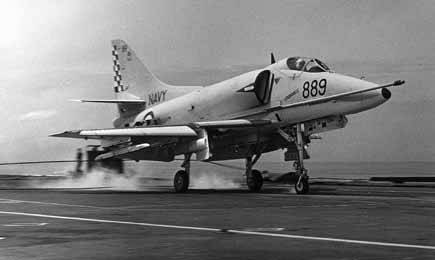
Skyhawk catching wire.

Mirror Control Officer.
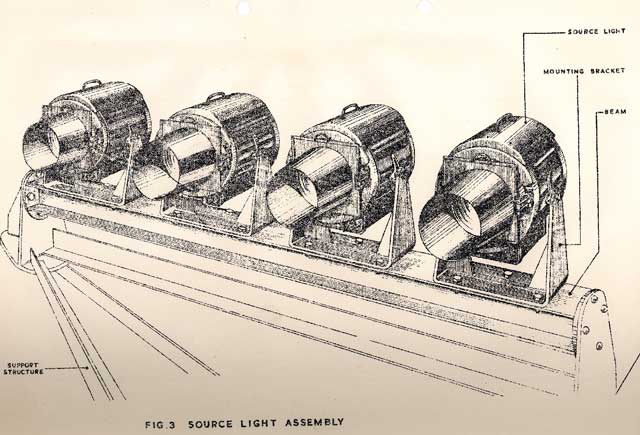
Source light assembly.
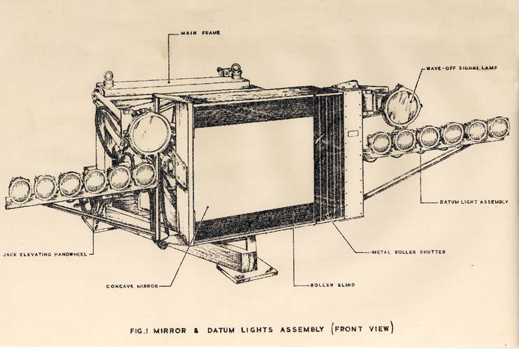
Mirror and datum lights assembly (front view).
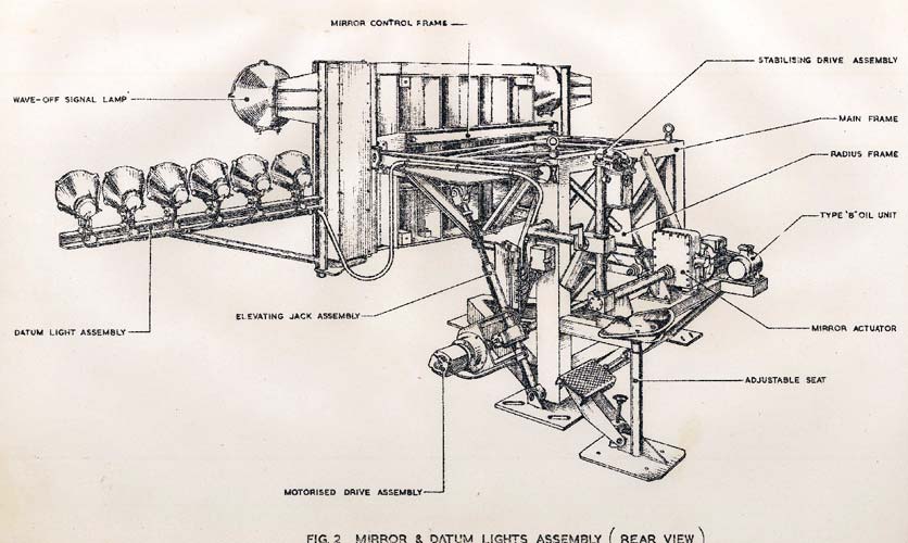
Mirror and datum lights assembly (rear view).
