HMAS
Sydney
(II) - Part 4

HMAS Sydney (II) wreck investigation


An initial examination of the wreck of HMAS Sydney confirmed that she had lost her bow and the visual evidence appeared to support much of what the German seamen had revealed concerning the action following their capture in 1941. Sydney’s bridge, mid-ships section and upper works were severely damaged and the accuracy of the German gunnery was apparent on each of her four gun turrets which had all received multiple direct hits.

The following picture compilations are provided to assist in interpreting the damage sustained by HMAS Sydney during her engagement with the Kormoran. The Sea Power Centre - Australia is grateful to the former Finding Sydney Foundation for the use of underwater imagery taken by search director David Mearns during the Remotely Operated Vehicle (ROV) inspection of the wreck.

Bow section

 
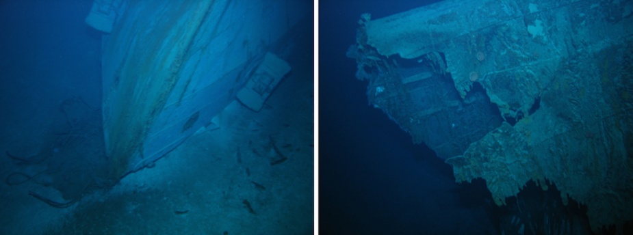
Sydney’s bow section. During the sinking sequence the bow severed from the main part of the ship and came to rest, inverted, on the seabed in the debris field.
The stem (front) of Sydney’s upturned bow section. Note the two anchors secured snugly in their hawse-pipes.
Sydney’s port anchor clearly visible on the bow section of her wreck. Right: A fine view of Sydney’s bow with both of her distinctive anchors in plain view.
A & B Turrets

 
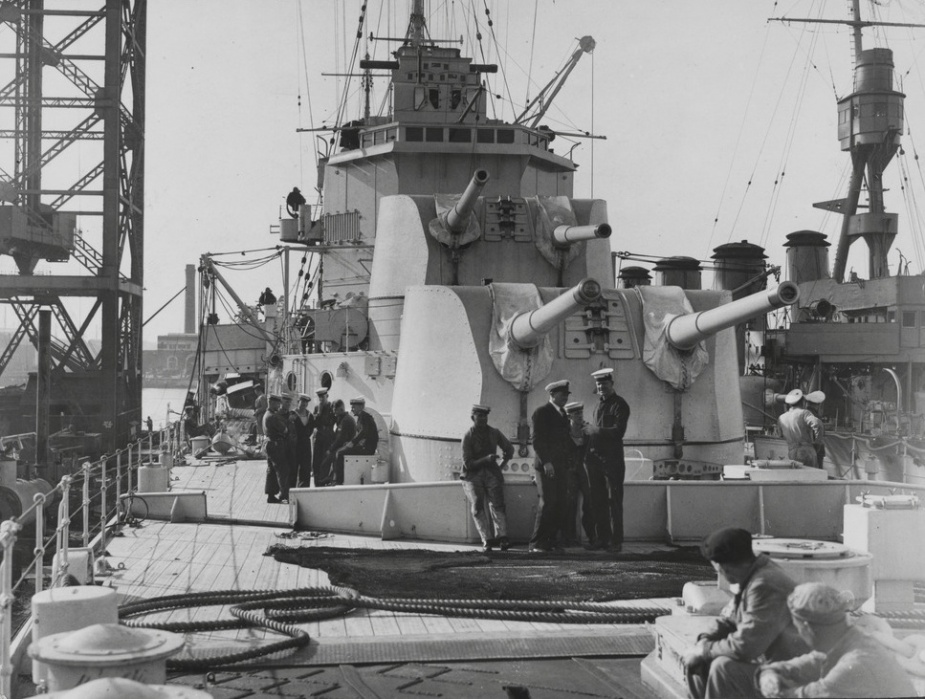
Ratings performing maintenance on the gun barrels of Sydney’s ‘A’ turret
Ratings performing maintenance on the gun barrels of Sydney’s ‘A’ turret. Visible in the open gun port can be seen the gun-layer’s Ross pattern monocular telescope.
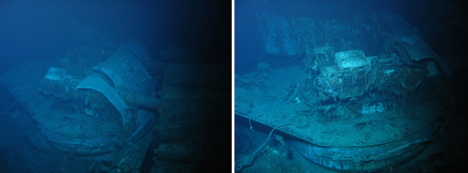
‘A’ turret showed signs of severe damage with most of its protective gun housing destroyed. Visible in these pictures can be seen the breeches of the twin Mark XXI 6-inch guns.
A view of both ‘A’ and ‘B’ turrets taken from Sydney’s foc’sle. Note the sighting ports visible between the 6-inch gun barrels.
‘B’ turret also showed signs of extensive damage. A large part of the turret ‘deck head’ (roof) was blown away and there was clear signs of armour piercing shell damage to the supporting barbette. Note that in these images the lower sighting ports are open, suggesting that the turret may have been operating in local control. The right hand sighting port (as viewed) is where a gun-layer rating would sit. The remains of his Ross pattern monocular telescope can be seen through the aperture. The left hand sighting port (as viewed) is where the gun-trainer would sit.
‘B’ turret also showed signs of extensive damage. A large part of the turret ‘deck head’ (roof) was blown away and there was clear signs of armour piercing shell damage to the supporting barbette. Note that in these images the lower sighting ports are open, suggesting that the turret may have been operating in local control. The right hand sighting port (as viewed) is where a gun-layer rating would sit. The left hand sighting port (as viewed) is where the gun-trainer would sit.
A general arrangement plan of the area at the front of one of Sydney’s Mk XXI twin 6-inch gun mounts indicating the positions in which the gun-layer, gun-trainer and sight setter would sit when closed up. The top of this drawing is indicative of the front of the gun turret.
Left: An expanded schematic of the gun-layer’s position. Right: An expanded view of the gun-trainer’s position. Both men are depicted facing forward.

Bridge, Director Control Tower and High-Angle Control Station

 
Sydney’s bridge and compass platform. Right: The bridge as viewed during the investigation of Sydney’s wreck. The forward bridge screen is severely damaged and the deck-head covering the compass platform has been torn away. It has been speculated that Sydney's bow may have crushed the forward part of the bridge when it separated from the ship at the time of her sinking.
Sydney was fitted with two 12-foot UK1 rangefinders on each side of the bridge. The port rangefinder was located lying inverted in the ship’s debris field.
The director control tower (DCT) dominated Sydney’s upper superstructure. It was used to direct the four 6-inch gun mounts that comprised Sydney’s main armament. Right: The badly damaged DCT was found in the debris field with Sydney’s distinctive compass platform deck-head resting against the front of it.
Sydney's 6-inch Twin Mark XXI Mounting, Director Control Tower, General Arrangement (DRG No: N9495).
The starboard side of the DCT as it lies on the seabed. Right: The base on which the DCT was mounted behind the compass platform. It too shows signs of severe damage from the impact of armour piercing shells.
The port side of the damaged DCT with Sydney’s compass platform deck-head visible to the left of the picture. Left: The rear of the DCT with it’s distinctive hatches, ladders and handrails visible.
Immediately behind the DCT was Sydney’s high-angle control station (HACS) that controlled Sydney’s secondary armament of 4-inch guns. The base of it was connected to the DCT mount by a distinctive bracing structure which can be seen here in the before and after images.
The tower on which the HACS was mounted sustained severe damage during the engagement with Kormoran and now lies in pieces in the debris field.
A schematic of Sydney's Mk IIIC High Angle Control Station. Visible in this drawing is the canvas hood which was normally folded back into the open position when the mount was in use.
A schematic of Sydney’s Mk IIIC High Angle Control Station. Visible in this drawing is the canvas hood which was normally folded back into the open position when the mount was in use.
The main part of the HACS lying on the seabed in the debris field. Remarkably the splinter mats that were lashed to the HACS to provide an additional measure of protection can be seen lying next to it, their rope lashing having long-since perished. In the right hand picture can be seen the remains of the rate officer's convoluted voice pipe.
The main part of the HACS lying on the seabed in the debris field. Remarkably the splinter mats that were lashed to the HACS to provide an additional measure of protection can be seen lying next to it, their rope lashing having long-since perished. In the right hand picture can be seen the remains of the rate officer’s convoluted voice pipe.
The rear elevation plan of the HACS indicating the ‘rate’ officer’s position and associated equipment.
Plan views of Sydney's HACS.
Plan views of Sydney’s HACS.

Foremast

 
Sydney was fitted with what was termed a ‘pole’ mast. Sitting atop of it was a ‘crow’s nest’ that was usually manned by a rating who would perform lookout duties. In this sequence the crow’s nest can clearly be seen along with voice pipes that were used to pass reports to the compass platform below.

Bakery

 
Sydney’s bakery and proving cupboard were situated on her port side, just astern of the crutches that secured two of her large ship’s boats. The plan of Sydney indicates the location of the proving cupboard and several other distinctive features associated with this area of the ship. In the imagery taken of this area during the wreck investigation can be seen the aft end of the boat cradle and the entrance to the proving cupboard where freshly baked bread would be placed to cool, safely secured behind the locked screen door.
A ‘then’ and ‘now’ image of the bakery revealing the distinctive features of the proving cupboard, including the adjacent ladder and unique screen door.
Left: A scene from happier times in the vicinity of Sydney’s bakery during ‘stand easy’. Right: This area of the ship suffered severe damage, as can be seen from this photo.

Funnels

 
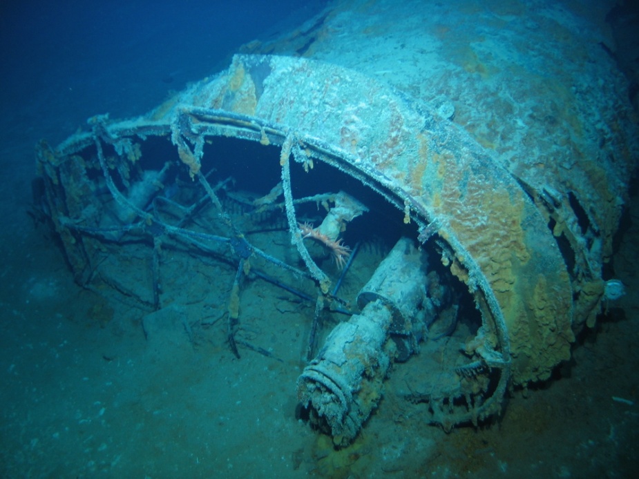
Two views of Sydney’s forward funnel. When Sydney sank it separated from the ship becoming entangled with 'Y’ gun turret.
Sydney’s aft funnel with two distinctive stove pipes visible protruding from its open top.
The aft funnel lying in the debris field with the two stove pipes seen in the preceding image clearly visible.

Boats

 
Sydney carried two 35-foot motor boats that were normally used to ferry personnel to and from the ship when at anchor or moored to a buoy. When not in use they were mounted on ‘boat crutches’ situated amidships, slightly forward of the ship’s bakery.
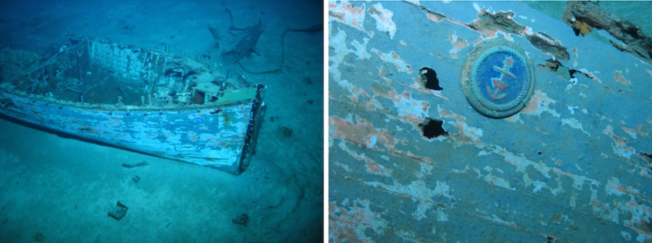
The remains of one of Sydney’s 35-foot motor boats lying in the debris field.
Left: Sydney's cutter coming ashore in Queensland waters. Right: The remains of the midship's cabin deck-head found in the debris field. Identifying features include brass handrails and the small spotlight visible in the picture at left.
Left: One of Sydney's motor boats coming ashore in Queensland waters. Right: The remains of the midship's cabin deck-head found in the debris field. Identifying features include brass hand-rails and the small spotlight visible in the picture at left.
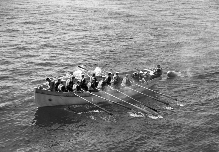
One of Sydney’s distinctive ‘clinker’ built cutters recovering a practice torpedo. Clinker built boats used planks that ran fore and aft with the lower edge of one plank lapping over the upper edge of the next below, like the slates on the roof of a house.
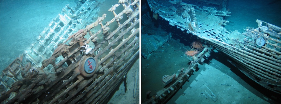
The tangled wrecks of two of Sydney’s boats lying in the debris field. The upper boat is likely one of Sydney’s 27-foot whalers.
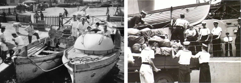
A cutter and motor boat from Sydney loading beer in Alexandria. Note the ships boat badge visible on the bows of both vessels.
A cutter and motor boat from Sydney loading beer in Alexandria. Note the ships boat badge visible on the bows of both vessels. Right: Ratings unloading mail in Fremantle. Visible in the background is one of Sydney’s 27-foot whalers.
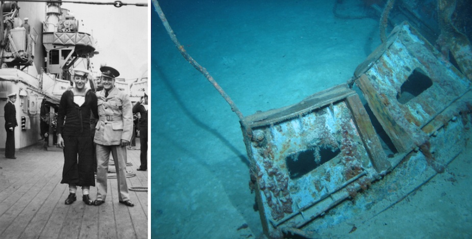
AB Martin James and Leading Aircraftman Keith Homard, pose on Sydney’s main deck. Visible in the background can be seen the distinctive boat crutches in which the ship’s boats were secured. The inboard boat crutch visible in this picture was located in the debris field as seen on the right.
AB Martin James and Leading Aircraftman Keith Homard (RAAF) pose on Sydney’s main deck. Visible in the background can be seen the distinctive boat crutches in which the ship’s boats were secured. The inboard boat crutch visible in this picture was located in the debris field as seen on the right.